News


NEW TB-2SRQD Quick Disconnect Programmable Anti-Tiedown Start Bar

NEW TB-2SRQD Quick Disconnect

Programmable Anti-Tiedown Start Bar

Quick Disconnect Programmable Anti-Tiedown Start Bar

The TB-2SRQD machine start bar is a complete OSHA compliant ergonomic two hand starting system. It increases productivity while operator fatigue and stress are decreased. It includes a cast aluminum enclosure, hand sensors and an anti-tiedown control with front panel indicator lights. New feature on this model, our hand sensors can now be installed, up to 12’, away from enclosure. This provides greater flexibility in confined workspaces. When properly installed, the TB-2SRQD meets OSHA requirements covering two-hand controls.

The start bar has a microprocessor and multiple modes of operation that can be programmed to fit various applications. It counts and displays machine cycles on the enclosure display.

Anti-tiedown – requires an operator to have both hands on start switches in order to start machine operation. This minimizes the possibility of the operator starting the machine while his hand is in the work area.

Control Reliability – designed to meet the OSHA classification of “control reliability” as defined in Sec. 1910.217(b)(13).

Redundant Output Contacts – uses double positive guided output relays. Each relay is checked for proper status prior to beginning a machine cycle.

Ergonomic – the angle of the hand sensors coincides with the natural movement of the hands and require no pressure to operate.

Safety – guarded hand switches allows actuation only from the side towards the machine operator.

Operation modes – multiple modes defined by setting options in the setup menu. These include Momentary Output, Maintained Output, Timed Output, Maintained Timed Output, Delayed Timed Output, Maintained Delayed Timed Output and Part-in-Place Mode.

Specifications: Physical Dimensions 50 cm x 10 cm x 6 cm (20″ x 3.75″ x 2.15″)
Weight 3 kg (6.5 lbs.)
Mounting Holes 2 vertical, tapped 1/4-20 – 2 horizontal, 1/4″ diameter
Power Supply 115 VAC or 220 VAC (factory configured)
Power Consumption 5 watts standby, 8 watts output energized
Input X1 NPN (sinking) type, 24VDC, 15mA. Typically used for Hold function. (PNP type optional, specify with order)
Input X3 PNP (sourcing) type, 24VDC, 15mA. Typically used for Reset function. (NPN type optional, specify with order)
Output X2 24 VDC, 0.1 Amps – 2 positive guided relay contacts in series, Life: 10 million cycles (mechanical)
Concurrency Timer 0.5 sec. (factory setting)
Environmental 0° – 60° C (32 – 140° F) ambient temp.
Origin Made in USA
Start Switches Electronic infrared photo sensors approximately 80 millisecond response time

View PDF


Vacuum Conveyors from MK Solutions

Vacuum Conveyors

Vacuum belt conveyors, or conveyors with a vacuum in them, are essential in today’s manufacturing environment. Vacuum conveyors can be used to hold flat parts to the belt’s surface, for elevation changes, or overhead conveying and are ideal for carrying small parts and operating at high speeds. A variety of vacuum sources can be used.

Vacuum Conveyor Specifications

North America offers a wide variety of vacuum conveyors, from widths of 50 mm (2”) all the way to 1200 mm (48”) and in a variety of lengths. Vacuum belt conveyors are made by using a perforated belt, and drawing air through a perforated or grooved slider bed; in either the GUF-2000 or GUF-P 2041 series flat belt conveyors. Because vacuum conveyors from mk are based on these popular flat belt conveyors, a wide variety of conveyor options are possible including drive type and location, motor voltage, idler diameter, and elevation. Furthermore, these conveyors are fully compatible with mk’s line of t-slot aluminum extrusion framing. The vacuum portion of the conveyor is also highly customizable to meet your specific needs. Conveyors can be designed with a single vacuum chamber (or area) or with multiple areas. The vacuum source can come from a number of different places, including fans built within the frame of the conveyor or from an external pump and blower. The conveyor can be supplied with or without the vacuum source depending on your particular needs.

Vacuum Conveyor Video and Contact

Check out this video from mk North America to see one of their vacuum conveyors in action. This particular model shows how it is possible to carry product from above using a vacuum conveyor and how rejected parts can be knocked out of the flow.


IAI Introduces the Remote I/O Unit

Introducing the Remote I/O Unit, Which Allows You to Easily Expand the Number of I/O Points on the Controller

Remote I/O Unit

  • Capable of Expanding the Number of I/O Points on the Controller
  • Small Product Size Easy Installation with DIN Rails
  • Easy Connection and Less Cables
  • The Front Panel LED Lights Make Unit Status Apparent
  • Compatible Controllers


Selecting a Rotary Indexing Table

Rotary indexing table use is widespread in automated assembly machinery and selecting the proper mechanism is essential for both maximizing performance and minimizing the cost of this critical component. This how-toguide will explore two common devices that can be used for rotary indexing and give advice for proper selection. These two popular devices are cam indexing drives and servo rotary tables.

Cam indexers are a ubiquitous mechanism that have been used for rotary tables for many decades. They are a great fit for applications that will always index the same angle and that require high-precision positioning at a very reasonable cost.

Servo Rotary TableA cam indexer uses a mechanical cam to provide the motion control to position the load. A mathematical motion curve is machined onto the cam that provides extremely smooth and repeatable motion.

A cam indexer has two main modes of operation. One mode is referred to as “Cycle-on-Demand”. This indicates that the camshaft will be cycled one revolution at a time to advance the output one position at a time. This is typically achieved by using an inexpensive camshaft sensor package to detect camshaft position and a VFD to stop and start the motor. The camshaft dwell period offers a wide window for the camshaft to stop without affecting the position of the output. To cycle the indexer, a PLC gives a command to the VFD to accelerate the drive motor to a preset speed, the cam rotates one revolution indexing the output, a sensor sends an in-position signal to the PLC, and the PLC signals the VFD to stop the camshaft during the cam dwell position. The table will be in the dwell position for however long is necessary to complete the work at each station. The dwell time can range from a fraction of a second to several minutes or hours depending on the application. This combination allows very accurate positioning with an inexpensive drive system.

A cam indexer can also be run in a more traditional “Continuous” mode where the camshaft spins at a constant speed and the indexing and dwell time is controlled solely by the cam motion profile. Continuous mode is useful when other equipment will be mechanically synchronized with the camshaft timing or when the indexer needs to run at cycle rates faster than a motor can be stopped and started. A continuous indexer can run at rates in excess of 1,000 cpm. The limitation of continuous mode is that it may be impossible to machine a cam that requires a quick indexing motion followed by a long dwell time.

A fully programmable servo rotary table is another common option. There are two specific cases where a servo rotary table is advantageous. The first is when a flexible motion pattern is required. An example is two different products being run on one machine that each require different indexing patterns. The other situation that suits a servo indexer is when extremely fast positioning is required followed by a long dwell period. A cycle-on-demand cam indexer is limited by the need to accelerate the camshaft up to speed during the dwell period Cam Indexing Mechanismbefore output motion is started. There are practical limitations to how fast the camshaft can be accelerated so there will be a delay before motion is started. With a servo rotary table, the output rotates as soon as the servomotor starts moving. A practical example would be a load being indexed 90 degrees in 0.25 seconds. This is not difficult for a continuous cam indexer or a zero-backlash servo indexer, but a cycle-on-demand cam indexer may struggle with that motion. For quick servo indexing applications, a preloaded gear reducer with zero-backlash is critical to achieving smooth indexing motions with minimal settling time. A zero-backlash RollerDrive mechanism would be an optimal choice to achieve accurate positioning with great dynamic response.
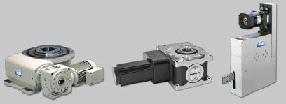
For either style of indexer, application information including moment of inertia, indexing angle, indexing time, and dwell time is required. A reputable manufacture should then be able to properly size the rotary table for the application.


Sankyo

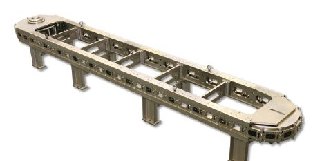
Sankyo Logo Precision Link Conveyor

Superior precision positioning products

IC80 Inline Chassis

Features

  • Open frame designs allows access all around
  • Tensioned with chordal compensating cam to reduce vibration
  • Link pins use needle roller bearings for increased longevity
  • Multiple drive options

Performance

  • Zero-backlash in all directions
  • High load capacity
  • Long-term accuracy
  • Fast and flexible indexing
Sankyo Automation provides innovative solutions with our family of high-speed,high precision positioning products…

  • Cam Indexers
  • Servo Rotary Tables
  • Part Handlers

Sankyo

SANKYO AUTOMATION (937) 498-490110655 State Route 47 | Sidney, Ohio 45365 www.sankyoautomation.com


Contact

317-862-9580

Location

Blettner Engineering Co., Inc.
8919 Southeastern Ave.
Indianapolis, IN 46239

Questions about assembly or automation solutions? Request Info